SELECTED WORK / PROJECT 001

Solaris Mk3Composite combustion chamber

Designing a lightweight chamber for a 10 kN hybrid rocket engine, then learning from its first hot-fire.

Mechanical designComposite manufactureStructural analysisSystems engineeringComponent integration
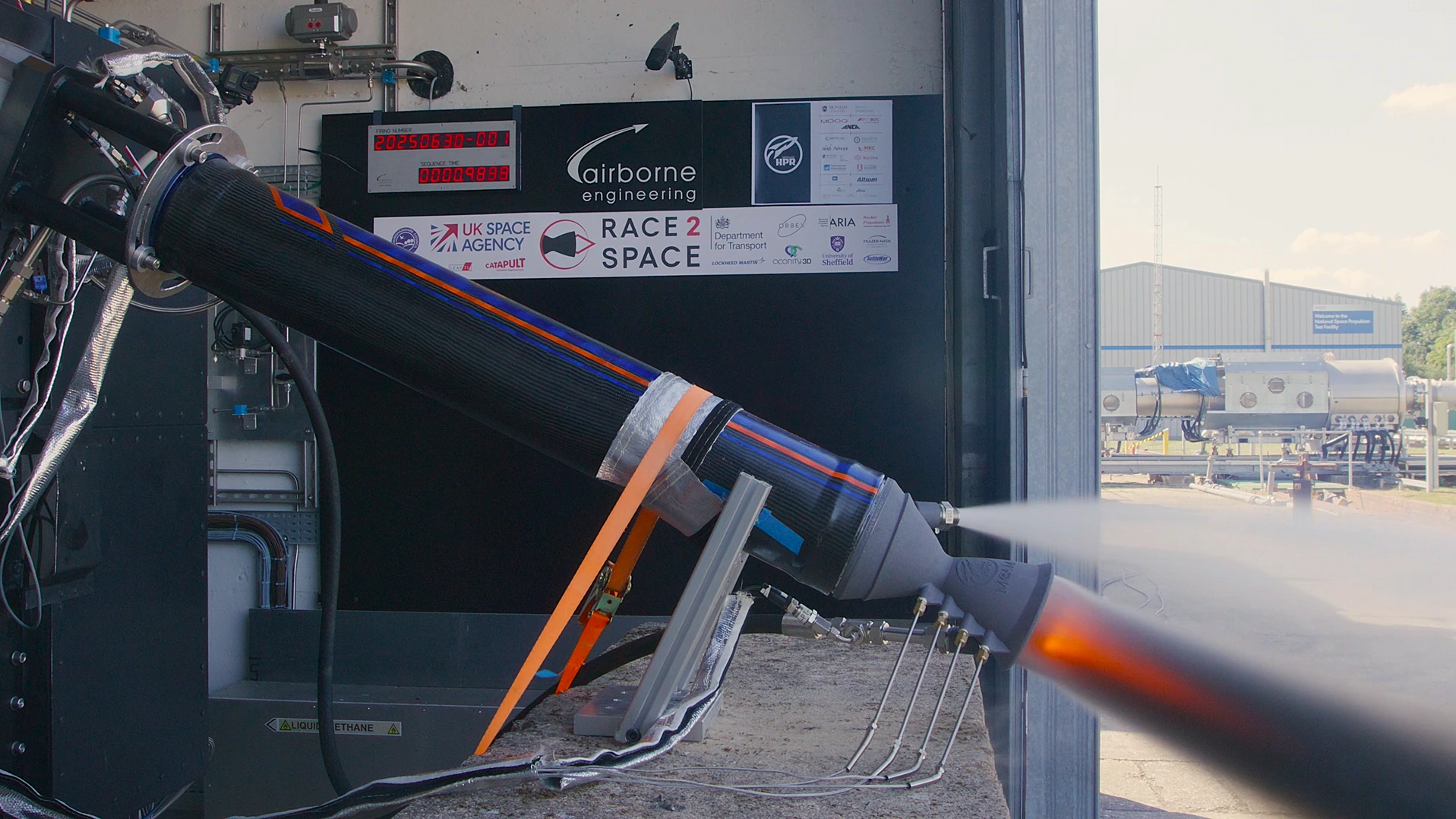
Solaris Mk3 on the AEL-J1 test stand in Westcott, UK, during the static-fire campaign
SOLARIS MK3 / AEL-J1 TEST FACILITYWESTCOTT, UK · 30 JUNE 2025
MY ROLE
Combustion chamber design
TEAM
Monash High Powered Rocketry
CONTEXT
Race2Space, United Kingdom
HOT-FIRE
30 June 2025

01 / THE CHALLENGE

A lighter
chamber.

The chamber needed to contain combustion pressure while keeping the engine light, serviceable and practical to manufacture within a student team.

My role focused on combustion chamber design. The wider propulsion team developed the injector, nozzle and supporting systems. This case study brings together my chamber work and the team's documented manufacture, modelling and test results.

Solaris Mk3 used liquid oxygen with a paraffin/ABS fuel grain. A composite overwrapped pressure vessel offered substantial mass savings, with aluminium couplers providing interfaces to the forward closure and nozzle.

10 kN

Engine design thrust

>60%

Documented design mass saving
versus an equivalent aluminium vessel

>3.0

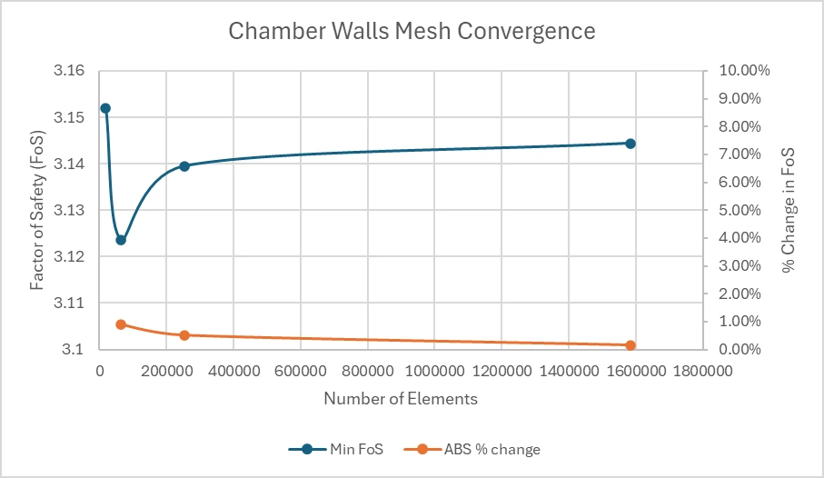
Composite design factor of safety

These are design figures. The hot-fire ended early following a nozzle retention failure.

02 / SYSTEMS ENGINEERING

Requirements.
Hardware. Evidence.

  • I designed the chamber internals, pressure wall and structural interface.
  • The design balanced strength, thermal protection, mass and manufacturing constraints.
  • The wider team’s analysis and test results informed the design.

FROM SPECIFICATION TO DESIGN DECISION

What the design had to satisfy

These values are design targets.

  • Strength: Target safety factors above 3 for composites and at least 2 for other components.
  • Thermal protection: Target a wall temperature below 150°C and isolate the pressure wall from combustion gases.
  • Serviceability: Allow assembly and cycling within 45 minutes, with a replaceable liner.
  • Fuel integrity: Support the paraffin and retain a protective fuel web during the intended burn.
  • Fit and sealing: Ensure the grain, liner and internal seals fit together reliably.
  • Component interfaces: Match the pre- and post-chambers to the fuel stack and nozzle.
  • Test-stand integration: Transfer thrust into the AEL stand while keeping sensors and fluid lines accessible.

03 / DESIGN & ANALYSIS

Composite shell.
Metallic interfaces.

The chamber combined a carbon-fibre structure with removable end interfaces. Explore the construction and the evidence behind it.

Engine cross-section

A shell built around the internal assembly

The documented chamber used 11 layers of 0/90 carbon-fibre twill, an inner fibreglass layer for thermal insulation and an external carbon sleeve for abrasion protection.

The structural laminate wrapped around the aluminium end couplers, connecting the lightweight shell to the removable forward closure and nozzle.

04 / MY COMPONENT DESIGN SCOPE

Inside the
complete assembly.

Seven component areas, connected by flow, thermal protection, sealing and structural loads.

My contribution covered these chamber components and their integration. The CAD and sections below show the team’s component designs. They show how design choices were constrained by neighbouring parts and the intended manufacturing route.

COMPONENT 01

Pre-combustion chamber

A protected space between the injector and the fuel grain, designed around the selected injector configuration.

The swirl configuration used a three-spoke phenolic baffle that also served as the pre-chamber. Its tapered spokes were shaped around the spray cones, while the upper surface shielded the forward closure. A separate, unbaffled phenolic pre-chamber accommodated the pintle injector.

The two variants shared an assembly envelope and standardised sealing interfaces. That made injector interchangeability, thermal protection, sensor and ignitor access, and practical machining part of the component design rather than separate afterthoughts.

INTERFACE RESPONSIBILITY
Injector / forward closure → pre-chamber → resonator and liner
Swirl pre-chamber CAD

COMPONENT 02

Post-combustion chamber

A mixing region aft of the fuel grain that also locates the internal stack and interfaces with the nozzle.

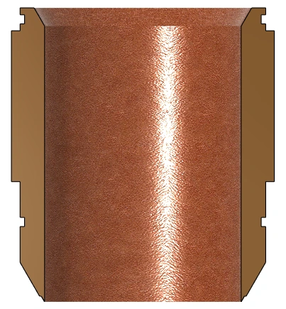
The post-chamber was designed with an L/D ratio of 1.5 to provide space for continued combustion. Phenolic was selected for thermal protection and suitability for manual machining. Lead-in and lead-out features shaped the transition through the assembly.

The nozzle acts against the post-chamber shoulder to compress the internal components. The taper, sealing grooves and mating lip therefore had to satisfy flow, insulation, alignment and mechanical support requirements together. The intended efficiency benefit was not demonstrated by the shortened hot-fire.

INTERFACE RESPONSIBILITY
Fuel grain / mixing plate → post-chamber → nozzle and liner seals
Post-chamber CAD

COMPONENT 03

Fuel grain

Combustion geometry had to work with the structural integrity and manufacture of the fuel itself.

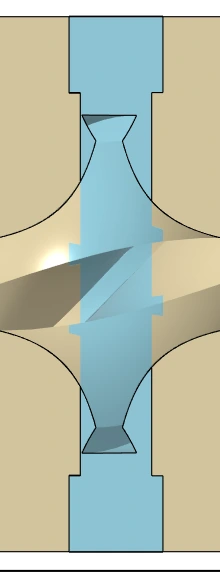
The grain combined paraffin with a printed ABS matrix using gyroid infill. The matrix supported the mechanically weak wax, while the wagon-wheel port was selected to shape burning area and regression behaviour. The design process compared multiple spoke arrangements before refining the geometry.

Three segments accommodated printer limits and allowed mixing plates between sections to address axial regression. Orientation features aligned the grain with adjacent plates and inserts. Controlled cooling was part of the manufacturing plan to reduce wax cracking and distortion; an even full-duration burn remained a test objective.

INTERFACE RESPONSIBILITY
Printed matrix + paraffin → liner fit → indexed plates and fuel inserts
Fuel-grain segment CAD

COMPONENT 04

Thermal liner

A replaceable thermal and gas barrier inside the load-bearing composite wall.

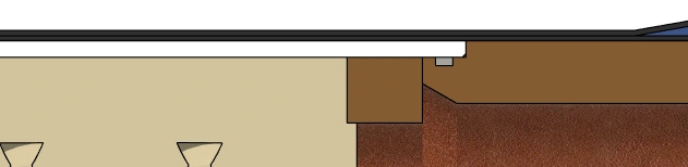
The PVC liner sat between the fuel grain and pressure vessel. Its purpose was to protect the wall from heat and combustion products, including a contingency if the fuel locally burned through. It was a separate internal component; the carbon laminate provided the principal pressure structure.

A continuous liner provided a common sealing surface for the internal stack. Standard pipe stock needed machining to the required fit, bringing availability, dimensional control, replaceability and sealing into one decision. The design specified o-rings and backup rings at the internal interfaces, with enduring thermal protection still requiring test evidence.

INTERFACE RESPONSIBILITY
Fuel grain → liner bore; internal component seals → liner → pressure shell
Liner and grain section drawing

COMPONENT 05

Combustion chamber wall

The pressure-carrying structure, designed for mass reduction and a manufacturable load path.

The wall combined structural carbon reinforcement with aluminium end couplers. Pressure containment, end-load transfer, thermal limits and serviceable threaded connections all constrained the design. Laminate and coupler calculations needed to be assessed together even though their models were separate.

Wet layup matched the team’s existing capability and available equipment. Ply configuration, consolidation, cure, mandrel release and coupler attachment became design considerations because they determined the hardware the team could actually produce. The detailed construction and prototype evidence are retained in the design and manufacture sections.

INTERFACE RESPONSIBILITY
Composite laminate → couplers → forward closure / structural adapter and nozzle
Pressure-wall CAD section

COMPONENT 06

Fuel inserts

A local change in regression behaviour intended to help control low-frequency combustion instability.

The proposed insert had 30% ABS infill compared with 20% in the surrounding grain. Its intended slower regression would leave a small step as the neighbouring fuel burned away, changing the boundary layer and flow behaviour.

The insert matched the fuel port and used the same indexing approach as the mixing plates. Common cutouts allowed grain sections, inserts and plates to remain interchangeable within the stack. This feature was a proposed stability strategy; the test results do not establish its effectiveness.

INTERFACE RESPONSIBILITY
Grain port → keyed insert → adjacent grain / mixing-plate stack
Fuel-insert CAD

COMPONENT 07

Structural interface

A controlled thrust path from the engine into the test facility, with space for the systems around it.

The two-part interface combined a slotted steel plate and an aluminium 6061-T6 adapter threaded to the chamber. Slots allowed orientation and clearance for lines, the ignitor and sensors. A floating rear support maintained alignment and resisted the engine’s weight moment while the forward interface carried axial thrust.

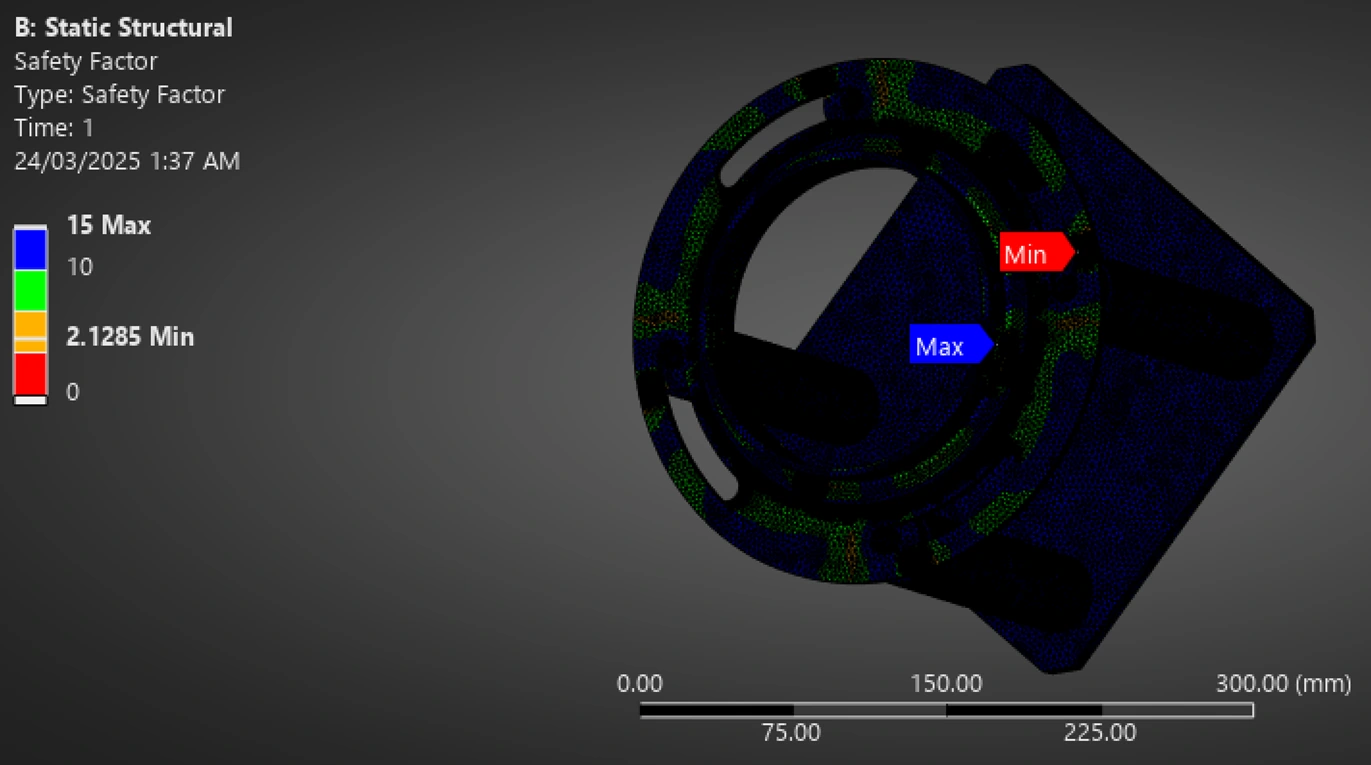
Separating the plate and adapter kept stock sizes practical and matched waterjet cutting to the plate and machining to the adapter. The team’s later mount analysis used 10 kN plus a CAD-derived moment and reported a minimum FoS of 2.13. This test-facility interface would need another design review for a flight installation.

INTERFACE RESPONSIBILITY
Chamber → threaded adapter → mounting plate → standoffs / facility load cell
Structural-interface CAD

05 / DESIGN EVOLUTION

A design shaped
by each review.

The MkIII architecture carried forward the Solaris family’s serviceable end connections while changing the wall, fuel system and internal flow-control features.

The move from MkII introduced a composite chamber, segmented fuel grain, mixing plates, resonator, baffles and fuel inserts. Further iterations refined the MkIII chamber and its manufacture.

The design history distinguishes proposed concepts, the later configuration and tested hardware.

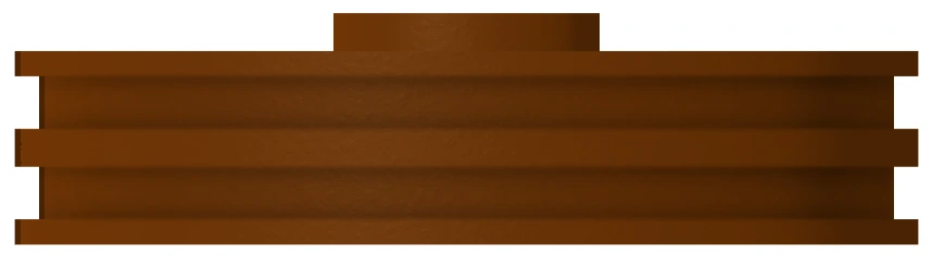
Earlier structural-interface concept

ONE EXAMPLE / THE MOUNT

Designing around the facility

The initial square-plate concept addressed the test-stand bolt pattern and thrust path. The later two-part slotted interface also addressed engine orientation and clearance for instrumentation and fluid lines.

The design criterion was a safe, accessible test-facility interface that the team could manufacture. A future flight interface remained a separate review task.

Compare the later interface
  • Pressure wall: The early PFA-film concept evolved into 11 carbon plies with fibreglass insulation.
  • Test-stand mount: A square aluminium plate evolved into a slotted steel plate and separate aluminium adapter.
  • Fuel geometry: Early grain concepts developed into a segmented assembly with keyed mixing plates and inserts.
  • Couplers: Outer ridges were added to the second chamber to improve attachment to the overwrap.

06 / MANUFACTURE & PROTOTYPING

Learning at
smaller scale.

Manufacturing capability shaped the design just as much as the structural calculations.

The team selected wet layup because it had experience with the process and could not access filament winding or AFP equipment within the project timeline. The selected epoxy system supported an elevated-temperature post-cure.

Three 60 mm test articles explored consolidation and the composite-to-aluminium interface. Their results exposed resin loss, mandrel-release difficulties and surface defects before the full-size build.

Composite chamber prototype with aluminium couplers
60 mm test article during wet layup

SMALL-PROTOTYPE RESULT

39 bar measured.
38 bar predicted.

The third 60 mm article ruptured in the fibre and matrix at 39 bar, close to the simulation's approximately 38 bar prediction.

This supported the team's small-article composite model. It did not qualify the full-size chamber or its nozzle-retention threads.

What the prototype iterations revealed
ArticleObserved outcome
01Resin loss and a flexible laminate. Hydrotesting encountered leakage and then thread shear.
02Improved stiffness, but the article could not be removed from the mandrel without damage.
03Successful release and a hydrostatic rupture close to the model prediction, with surface imperfections still present.

07 / THE HOT-FIRE

The first
hot-fire.

On 30 June 2025, the team tested the chamber at Airborne Engineering's AEL-J1 facility in Westcott, UK.

The facility supplied liquid oxygen directly. This campaign tested the combustion chamber rather than the complete flight configuration and its own fluids system.

The test ended early when the nozzle detached. The planned nitrogen purge activated after the failure.

  1. 0.90 s

    Pressure builds

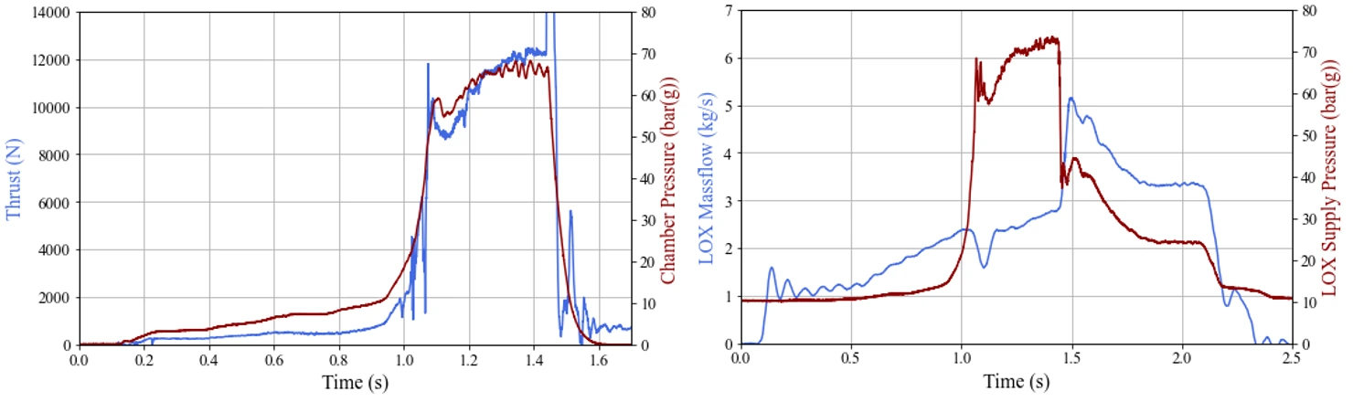
    Chamber pressure reaches approximately 60 bar following liquid ignition.

  2. 1.026 s

    Thread slip visible

    The test footage shows the nozzle visibly skipping a thread.

  3. 1.45 s

    Nozzle separates

    Nozzle retention fails and the nozzle leaves the aft end of the chamber.

Times relative to LOX flow commencement.

Test start-up sequence
Inspect the recorded test plots

POST-TEST INVESTIGATION

What the hardware
revealed.

Observed damage

Inspection found sheared aluminium coupler threads, outward deformation of the rear coupler and two cracks in the composite overwrap.

The team's analysis

The coupler threads had been machined with an unintended double start. Modelling of the out-of-specification geometry produced a factor of safety of approximately 0.9–1.1 under the test loads and deformation consistent with the observed damage.

This supported the team's conclusion that the manufactured thread geometry was a key contributor to failure.

The team requested independent inspection by ATTAR; those findings are unavailable, so this remains the team’s internal investigation.

Post-test inspection
Coupler failure model

08 / REFLECTION

The lessons
I take forward.

This project made the connection between design assumptions and manufactured hardware very concrete.

Bringing a new chamber to a test facility was a significant team achievement. The early failure also showed how a critical manufactured feature can invalidate the margin calculated for the intended geometry.

The next iteration needs evidence that the hardware matches the model, alongside evidence that the model represents the loads.

01

Inspect the features that carry the load

A calculated safety factor depends on the specified geometry. Critical interfaces need recorded checks before assembly and testing.

02

Model the part that was manufactured

Post-test analysis of the actual thread geometry explained behaviour that the intended design model could not capture.

03

Keep prototype validation in context

A close small-article burst prediction is useful evidence for a composite model. Full-size interfaces and manufacturing quality still need their own validation.

JERRY SUN / ENGINEERING PORTFOLIO

Back to selected work